


Howdy, Stranger!
It looks like you're new here. If you want to get involved, click one of these buttons!

Categories
- 654 All Categories
- 218 General
- 70 Ask an Evil Mad Scientist
- 6 Blog Projects
- 13 Electronics
- 16 Microcontrollers
- 10 Software Tools
- 0 Fabrication Technologies
- 436 Product Support
- 76 AxiDraw
- 26 WaterColorBot
- 172 Egg-Bot
- 2 AYAB
- 57 Clock Kits
- 23 Larson Scanner and Menorah
- 40 LED Matrix Kits
- 38 Other kit and product support
LED drivers, Fall in!

Hi Everyone,
In my never-ending quest for more blinky lights, here are some LED drivers I’ve found around the Interweb, and even a few weaks I’ve made. This stuff is fairly simple, and you’ll see circuits like this all over the place, but I thought I’d bring some of them together in one place here.
Why use a driver circuit? Well, the best reason is to avoid loading down the circuit the LED is attached to. If you load down a circuit like an LFO, it can change the LFO’s output level or even affect the frequency, and asking a CMOS chip to directly drive an LED can result in erratic operation or even damage to the chip. For example, the 4017 used in many simple sequencers can only supply about 8mA (and that’s the max rating – you generally don’t want to depend on that for long term operation). If you actually wants to know LED Driver Basics and Its Circuit Design, I found this is a fantastic guide that explains what LED Driver is, http://www.apogeeweb.net/article/78.html, highly recommended read.
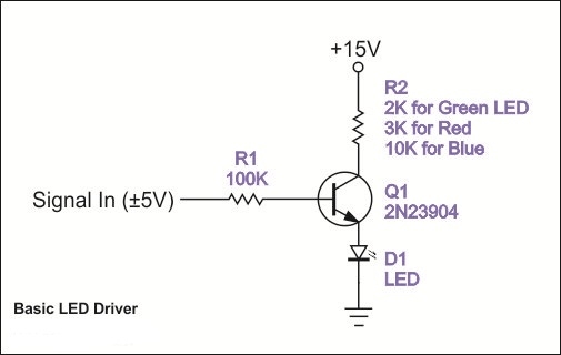
Of course, here’s the classic. An NPN transistor actually supplies the current to the LED, and the amount of current required from driving circuit is minimal. This circuit works well with digital or analog inputs, and is dirt simple. R1 sets the current to the base of the transistor - I’ve used a wide range of values from 10K to 150K. R2 sets the current through the transistor and into the LED. Most LEDs can take up to 20mA (0.020A), but you can usually get away with MUCH less than this and still have a very visible indicator. Use Ohm’s Law (I = V/R) to figure out how much current you’re putting through your transistor and LED. For example, in the circuit below with a +15V supply and a 2K resistor, we’re running about 7.5mA (15 / 2,000 = 0.0075A) through the green LED. The protection diode D2 is recommended if the input signal goes more negative than -6V (this is the base – emitter “breakdown voltage” for the 2N3904 and negative voltages greater than this will damage the transistor).
Let’s not forget that there are problems with LEDs. They consume a relatively large amount of current, and they can switch on and off very quickly. This means that your power supply is suddenly expected to deliver an extra 10 or 20mA, and can cause a spike through the supply and every circuit connected to it, resulting in switching noise getting into your audio. One solution is to use as little current through the LED as possible. It can vary with the color and brand of LED, but just a few milliamps can be enough in many cases. Experiment with a larger value current limiting resistor (R2), and see what works. Another thing I do with my LFOs is to run the LED off the triangle wave rather than the square. This turns the LED on and off more gradually, and gives the power supply and filter capacitors throughout the system more time to supply the necessary current. If all you have available is a square wave, you might want to try adding a capacitor to ground after R1. This forms a low pass filter and can help round off the sharp edges of the switching signal going to the transistor.
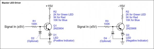
The LED driver pictured above is very handy, and is about as simple as is gets, but there are a few things I don’t like about it. The first is that it doesn’t show the negative half of the waveform. Well, adding a second circuit using a 2N3906 and the negative supply solves that. Smile The circuit here is still fairly simple and now shows both halves of a bipolar wave. There’s still one thing that bugs me – the LED’s don’t come on until they have a few volts across them (approximately 1.7 for red LEDs, 2.1 for green, and 3.4 for blue). This means that they don’t show the transitions around 0V. For a slow moving LFO signal, this can take several seconds.
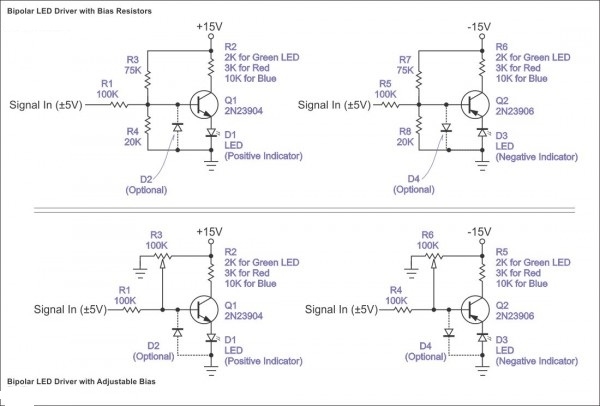
So to have our indicator show the lower voltages around 0V, we need to bias the input signal by adding a volt or two to it. This forces the LED to come on earlier and lets us monitor the changes around the 0V area better. This is basically the same thing as biasing an audio amplifier to reduce crossover distortion. You can use a couple of resistors as a voltage divider to add a volt or two to the input signal and bias it up (or down in the case of the negative voltage monitor). The values I’ve shown should be close, but you may want to experiment to get the effect you like. We’re looking for the LED to come on when the input signal is just barely above (or below) 0V. What I really like is the second solution with the adjustable bias trimmers. Put in a 100K (or even 1M) trimmer, and adjust it so that the LED comes on when you like. You can even set them so they come on just before the signal crosses the 0V line. If you don’t want to ‘waste’ a trimmer, just measure the resistance between the trimmer’s legs, and substitute the closest available fixed resistors. I’ve set mine so that there is a bit of overlap – the LEDs are both on (dimly) during the crossover around 0V. It makes a great indicator for the odd waveshapes on the LFX, and the whole mess consumes only about 7 or 8mA.
Also, since the current through the LEDs is inversely proportional (when one is high, the other is low, and there is overlap in the middle where both are at lower levels), the system has a relatively stable power draw. It seems to vary from 5 to 8mA, but doesn’t swing from 0 to 20mA like some LED circuits. You still need to make sure your power supply has enough current capability before you add LEDs, but this setup is a little more “gentle” as far as sudden current swings and spikes.
One more thing: blue LEDs aren’t necessarily evil, but most of the time they are too darned bright! Don’t be afraid to throw in a really big current limiting resistor (like 10K or even 20K). Also, I stack the LEDs, putting the blue one BEHIND a red or green diffused LED. It can be a bit of a challenge to mount (try putting the first LED in a regular panel mount and then using heat shrink tubing to fix the second one behind it), but the color combinations can be really nice.
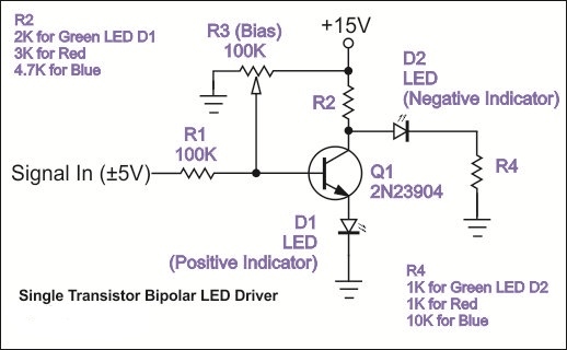
And now for something completely different... I was wondering if I could run two LEDs off of a single transistor, one off the emitter, and one off the collector (in inverting mode). Turns out you CAN do this Wink This circuit doesn't have quite the range of the two-transistor model, but it's very close and uses fewer parts. This version is also more sensitive to the bias setting, but just apply a nice slow triangle wave and adjust the bias so that the two LEDs stay on for the same amount of time. I've also used this setup with a green LED for D1 and a blue LED for D2. Don't be afraid to experiment with different resistor values. I've used a 15K for R4 with a blue LED, and that tames it down quite a bit. Makes a pretty light show.
Enjoy!